In this article I will show the build of a quadcopter made with a 450 frame kit using APM 2.6 with ArduCopter firmware version 3.2.1 as controller: this system performs attitude control and can be programmed for the execution of autonomous missions using PC (via Mission Planner software) or Smartphone (via DroidPlanner app).
Components list
In this section it is reported a list of the components used for this project with a short description of their most important features and a link to it. In the case I cannot find the same component I used, I have put a link where you can buy a similar one.
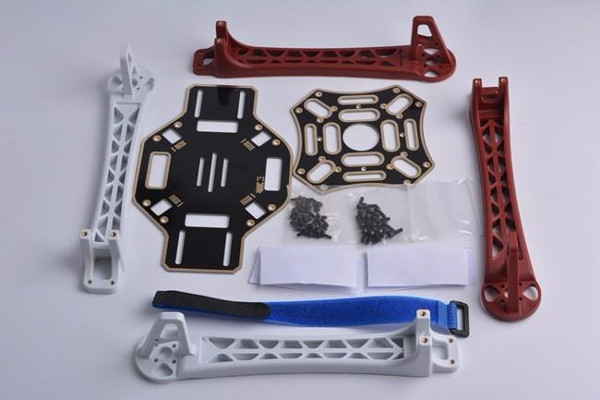
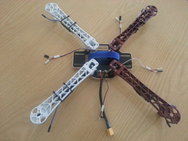
This frame is a nylon and fiber glass structure: the number stands for the length of each line of the cross frame, i.e. 450 mm (considering the distance from propeller center of rotation to the opposite one).
As the previous image shows, this frame has an integrated power distribution board (PDB) which simplifies the connections reducing the number of wires floating around the aircraft.
I chose to have the red arms as the front of the quadcopter, while the white ones represent the rear (this is a completely arbitrary choice and depends on how the controller is oriented).
- APM controller kit
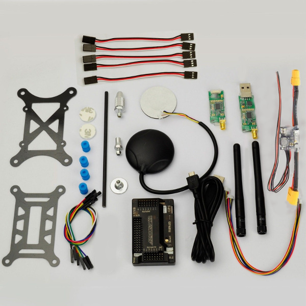
The main component of this kit is the controller, the APM:
The arrow with the “Front” tag indicates the direction that the controller interprets as forward.
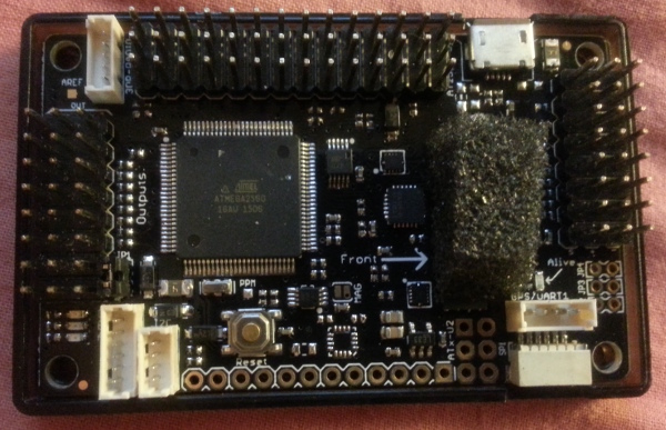
It features an Atmel ATmega 2560 microcontroller and a series of sensors like gyroscope, magnetometer and barometer (the last one is covered by foam to reduce disturbances). It has ports to connect GPS, telemetry and power module. It features also a series of inputs and outputs pins respectively for receiver channels and ESCs (Electronic Speed Controllers) command signals.
There is also a port for connecting the board to a PC through USB in order to install/update the firmware or programming the APM.
A particularly important element on the circuit is the jumper JP1: depending on the chosen power configuration (using power module or taking power from ESCs) you have to remove it or leave it in place:
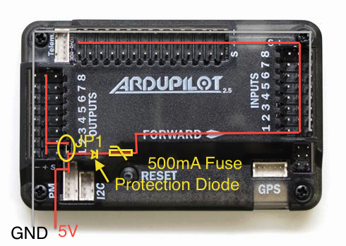
In this case, since we are going to use a power module that distributes the power along the board, we have to remove JP1. Moreover, since the ESCs have a BEC (Battery Eliminator Circuit) we need to connect only the signal wire and leave the positive and black wires disconnected.
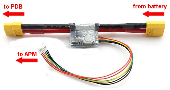
This kit, other than the APM controller, includes the following components: CRIUS power module, GPS, telemetry modules (TX and RX), shock absorber and connection cables.
The power module converts battery voltage (LiPo 3S or 4S) to the proper stable voltage of 5.3V (with a maximum current of 2.25A) needed from the controller and delivers it also to the ESCs; it also measures battery voltage and current consumption, and sends these data to the APM.
The GPS and telemetry TX module are used to transmit respectively aircraft position and general flight data like attitude or battery consumption to the ground station (e.g. PC or Smartphone) where the telemetry RX module is plugged in; telemetry works at a frequency of 433 MHz.
The shock absorber is used as a mount for the controller and helps getting less vibrations so as to improve compass reading.
Before mounting the APM control board on the quadcopter we need to upload the firmware like described here and perform magnetometer (compass) and accelerometer calibration following the links to the guides at the end of that article (radio control calibration can be done even after the structural build).
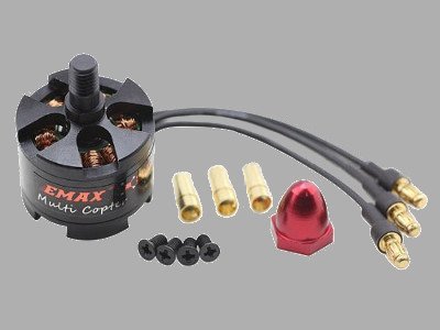
- 4 x Propellers 1045
Each brushless motor comes with a pair of propellers, one normal (for clockwise rotation) and another pusher (for counterclockwise rotation). Nuts have different colors since they are made to lock propellers in the opposite direction they spin (self locking nuts, so depending on motors rotation two of them lock in CW direction and the others CCW).
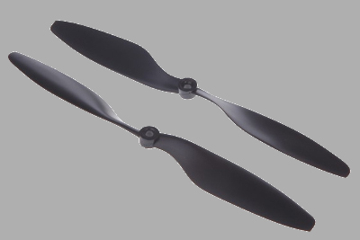
Motors manual suggests to use the provided 10x4.5 propellers with 3S LiPo battery and this is the configuration we are going to set up.
The maximum Thrust for each motor is given by (0.850 Kg x 9.8 m/s^2) = 8.33 N.
However, as indicated in the manual, it is also possible to set up a configuration with 8x4.5 propellers and 4S LiPo battery.
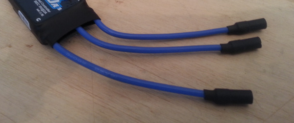
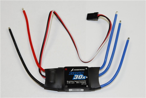](/images/quadcopter_450_build/esc.jpg)
These ESCs support 2S to 4S LiPo battery and have a BEC that provides and output of 5V@2A, so we need to keep this in mind when connecting to the APM controller.
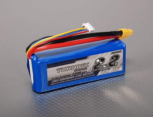
These are pretty classic 3-cells LiPo batteries with 25C discharge rate. They provide, for my configuration, a flight time of 8-9 minutes depending on the flying style.
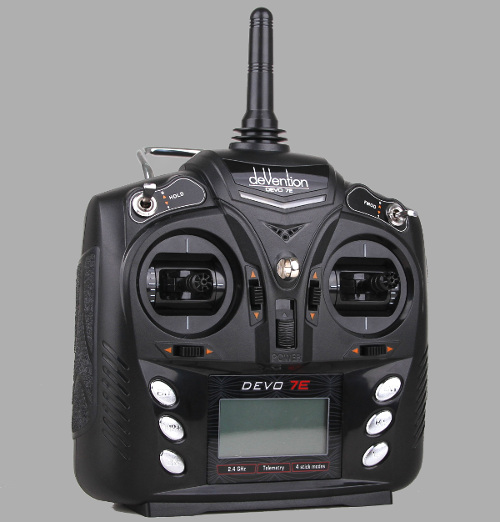
This is my favorite transmitter since it supports Deviation firmware, a community project that can be loaded on the Devo 7E by substituting the original software; its main feature is that it permits to bind to almost all commercial RC systems by simply adding some Radio Frequency (RF) modules (we will talk about that in other articles): in this way you can go to the field with a single TX controlling all your models.
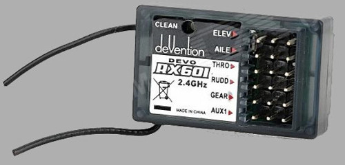
This is a basic 6 channel receiver I had laying around; I will probably substitute it in the future in case I will need a wider control range.
Other necessary items for this build are reported here:
- Expandable Sleeving Cable 2m (diameter 1 cm);
- Heat shrink tubing 2m (diameter 0.7 cm and 1.5 cm);
- Insulating tape;
- Nylon zip ties 2.5 mm x 150 mm;
- 14 AWG power cables;
- XT60 connectors;
- Decent soldering iron, hot glue gun and cutter.
Build
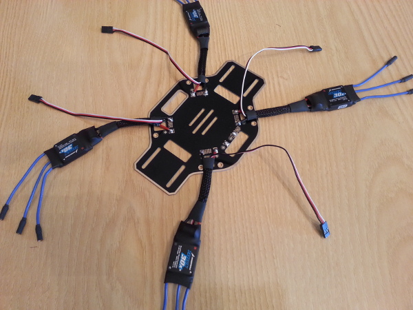
We can start the build by analyzing the power distribution on the quadrotor frame:
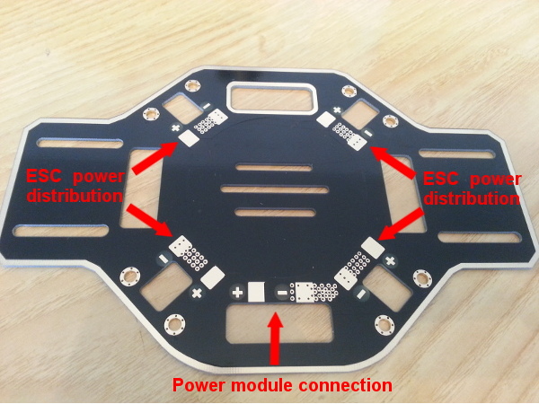
As the image shows, we have to solder ESCs power leads to the board in the points indicated by the upper four red arrows, being careful to connect the black wire of each ESC, i.e. the negative lead, to the “-“ and the red wire, i.e. the positive lead, to the “+”.
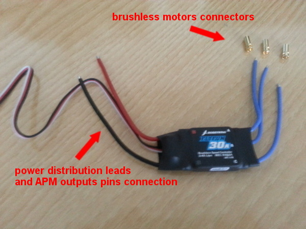
Before doing that we need to solder the brushless motor connectors provided with the motors themselves to the four ESCs:
To insulate the ends, we cut 3x4 short sections of heat shrink tube with diameter 0.7 cm and fix them around the connectors just by using hot air:
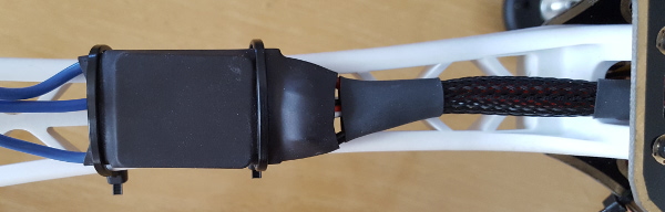
After passing ESCs power leads wires inside the expandable sleeving cable, that can be blocked in place using heat shrink tube with diameter 1.5 cm, we can proceed with the soldering:
It is a good practice to cover the power contacts on the board with hot glue just to be sure they are isolated.
We can now proceed by preparing the 14 AWG cable for power connection: one side of the positive/negative wires has to be soldered on the board, while the other one needs a XT60 connector in order to plug in the power module.
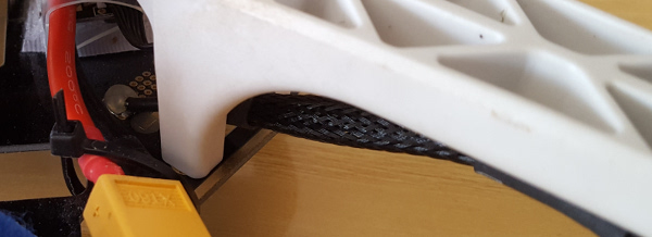
We can also lock the arms to the power distribution board with the screws, having care to pass ESC wires inside the arm like in the following picture:
Then we can mount the ESCs on the four arms which is the best solution to achieve two objectives: good cooling of their circuit and distributed weight for proper balance; each one of them can be fixed with two zip ties:
After these steps, remembering to isolate the positive and negative leads of the ESCs (we need only the white signal wire for the reason explained before), we have the following result:
For CRIUS power module connection we simply follow this scheme:
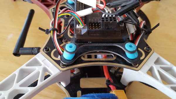
We can then mount the top plate using the screws included with the frame and fix the shock absorber structure with the APM controller on using some zip ties. This positioning has been chosen because as stated in Ardupilot website referring to the controller: “It should be placed close to the center of gravity of the vehicle (both horizontally and vertically). Generally this means it should be placed within a few centimeters of the middle of the vehicle and level with the motors.”
GPS with its shaft can be fixed through one of the holes in the top plate; we need to be careful orienting the front of it in the same way as the controller, i.e. towards the red arms. Instead telemetry transmitter module can be positioned on the bottom plate. GPS and telemetry module can be easily connected to the ports with their referring tags.
Regarding APM Inputs pins connection, we can follow up this scheme:
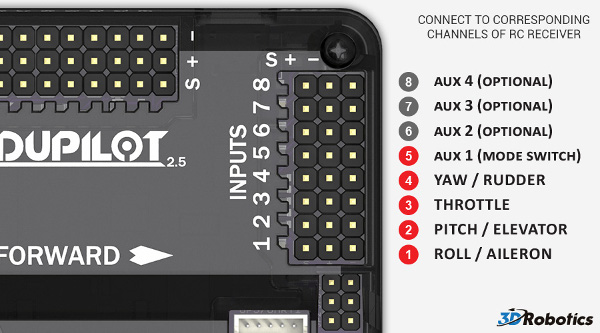
So we just follow the reported connections, keeping in mind that we need to take the power for the receiver only from one positive pin (mid rail) from the APM, the other channels need just the signal wire (white).
Instead for APM Outputs pins connection, we can follow up this scheme:
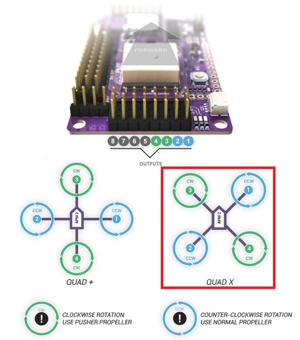
I have chosen to use “Quad X” configuration, i.e. the one highlighted with the red rectangle:
- Motor 1 - CCW rotation with normal propeller;
- Motor 2 - CCW rotation with normal propeller;
- Motor 3 - CW rotation with pusher propeller;
- Motor 4 - CW rotation with pusher propeller.
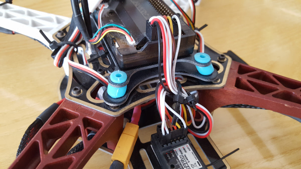
As the following image reports, only the signal wire (white) from the every ESC has been connected to the controller:
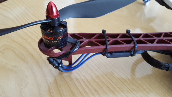
Finally we can mount motors and propellers, with particular attention to rotation direction and propeller/nuts type; the following picture shows a CCW rotating motor with a pusher propeller blocked by the corresponding red nut:
It is always a good practice to group cables using zip ties in order to avoid collisions with the blades and have a clean result.
The following image shows the final product, which has a weight of 0.9 Kg without battery:
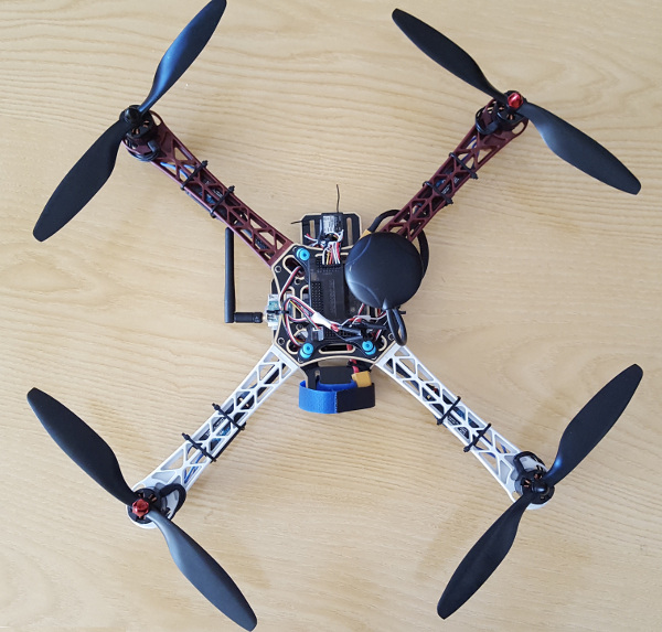
You may notice pieces of transparent tape on the blades: they are there to balance propellers weight.
Next steps
Right now we have the finished structure with everything mounted on, but we need to check if motors are rotating in the proper direction (if not, it is just a matter of inverting one of the three motor cables connected to the ESCs). By doing this, for safety reasons, remove the propellers from the motors.
Once we are sure everything is properly set up, we can go with our first test and start tuning PID (Proportional-Integral-Derivative) gains.